
Rotary encoders: Raise a Glitch Storm | Hackspace 34
from Raspberry Pi Blog – Raspberry Pi
Author Ben Everard
A Glitch Storm is an explosive torrent of musical rhythms and sound, all generated from a single line of code. In theory, you can’t do this with a Raspberry Pi running Python – in this month’s new issue, out now, the HackSpace magazine team lovingly acquired a tutorial from The Mag Pi team to throw theory out the window and show you how.
What is a Glitch Storm
A Glitch Storm is a user-influenceable version of bytebeat music. We love definitions like that here at the Bakery: something you have never heard of is simple a development of something else you have never heard of. Bytebeat music was at the heart of the old Commodore 64 demo scene, a competition to see who could produce the most impressive graphs and music in a very limited number of bytes. This was revived/rediscovered and christened by Viznut, aka Ville-Matias Heikkilä, in 2011. And then JC Ureña of the ‘spherical sound society’ converted the concept into the interactive Glitch Storm.
So what is it?
Most random music generators work on the level of notes; that is, notes are chosen one at a time and then played, like our Fractal Music project in The
MagPi #66. However, with bytebeat music, an algorithm generates the actual samples levels that make up the sound. This algorithm performs bitwise operations on a tick variable that increments with each sample. Depending on the algorithm used, this may or may not produce something musically interesting. Often, the samples produced exhibit a fractal structure, which is itself similar on many levels, thus providing both the notes and structure.Enter the ‘Glitch Storm’
With a Glitch Storm, three user-controlled variables – a, b, and c – can be added to this algorithm, allowing the results to be fine-tuned. In the ‘Algorithms’ box, you can see that the bytebeat algorithms simply run; they all repeat after a certain time, but this time can be long, in the order of hours for some. A Glitch Storm algorithm, on the other hand, contains variables that a user can change in real-time while the sample is playing. This exactly what we can do with rotary encoders, without having the algorithm interrupted by checking the state of them all the time.
What hardware?
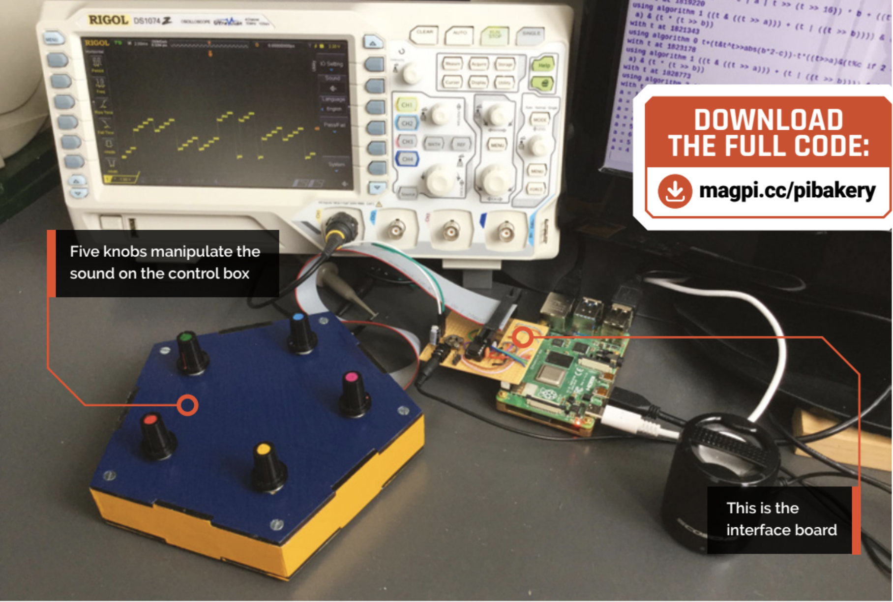
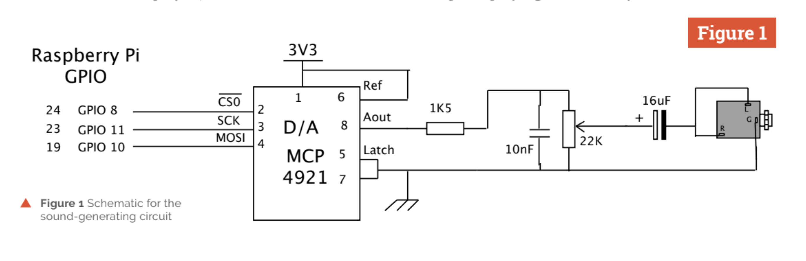
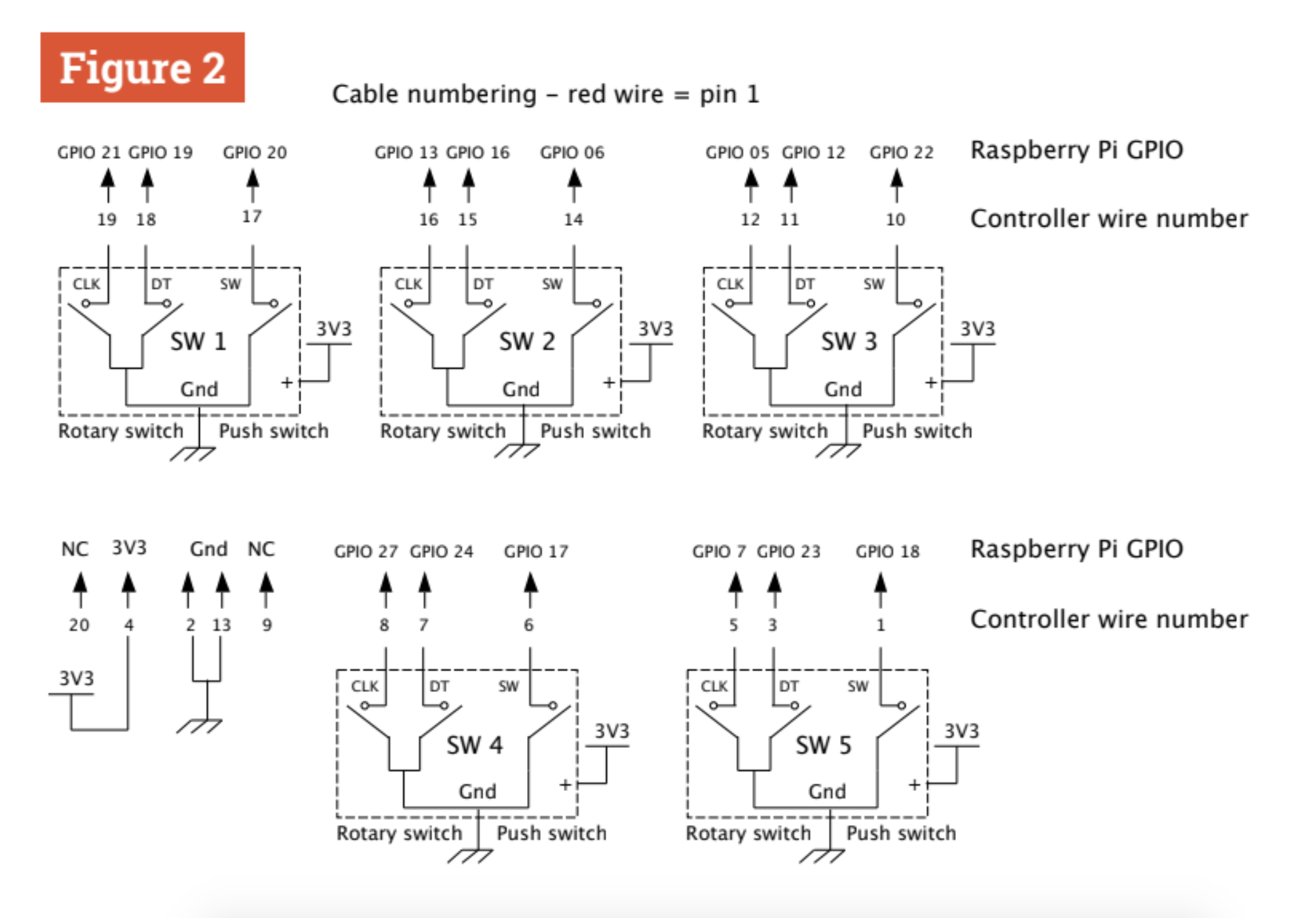
In order to produce music like this on the Raspberry Pi, we need some extra hardware to generate the sound samples, and also a bunch of rotary encoders to control things. The samples are produced by using a 12-bit A/D converter connected to one of the SPI ports. The schematic of this is shown in Figure 1. The clock rate for the transfer of data to this can be controlled and provides a simple way of controlling, to some extent, the sample rate of the sound. Figure 2 shows the wiring diagram of the five rotary encoders we used.
Making the hardware
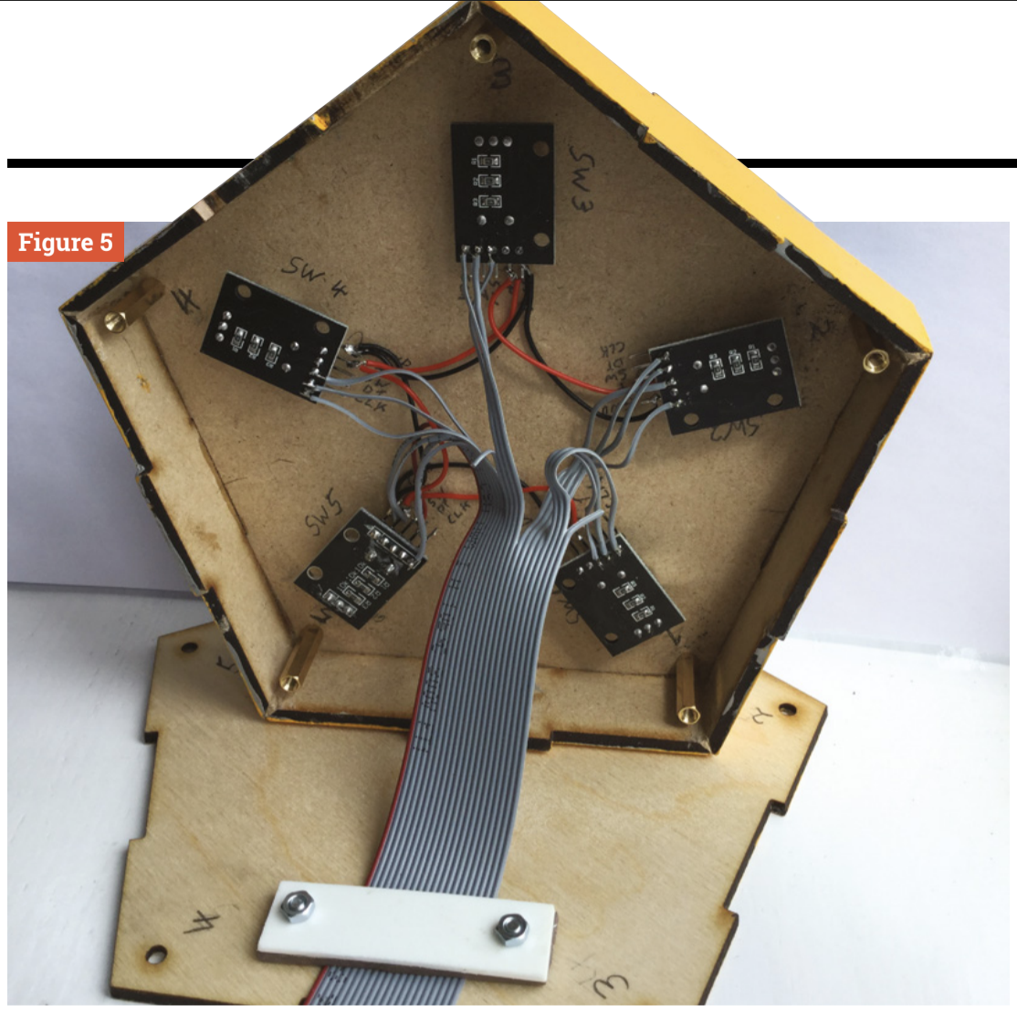
The hardware comes as two parts: the D/A converter and associated audio components. These are built on a board that hangs off Raspberry Pi’s GPIO pins. Also on this board is a socket that carries the wires to the control box. We used an IDC (insulation displacement connector) to connect between the board and the box, as we wanted the D/A connection wires to be as short as possible because they carry a high frequency signal. We used a pentagonal box just for fun, with a control in each corner, but the box shape is not important here.
Construction
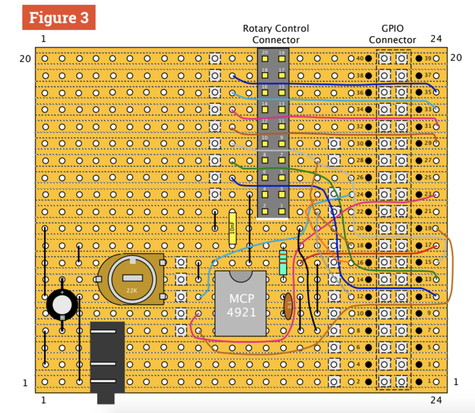
The board is built on a 20-row by 24-hole piece of stripboard. Figure 3 and Figure 4 show the physical layout for the front and back of the board. The hole number 5 on row 4 is enlarged to 2.5mm and a new hole is drilled between rows 1 and 2 to accommodate the audio jack socket. A 40-way surface-mount socket connector is soldered to the back of the board, and a 20-way socket is soldered to the front. You could miss this out and wire the 20-way ribbon cable direct to the holes in these positions if you want to economise.
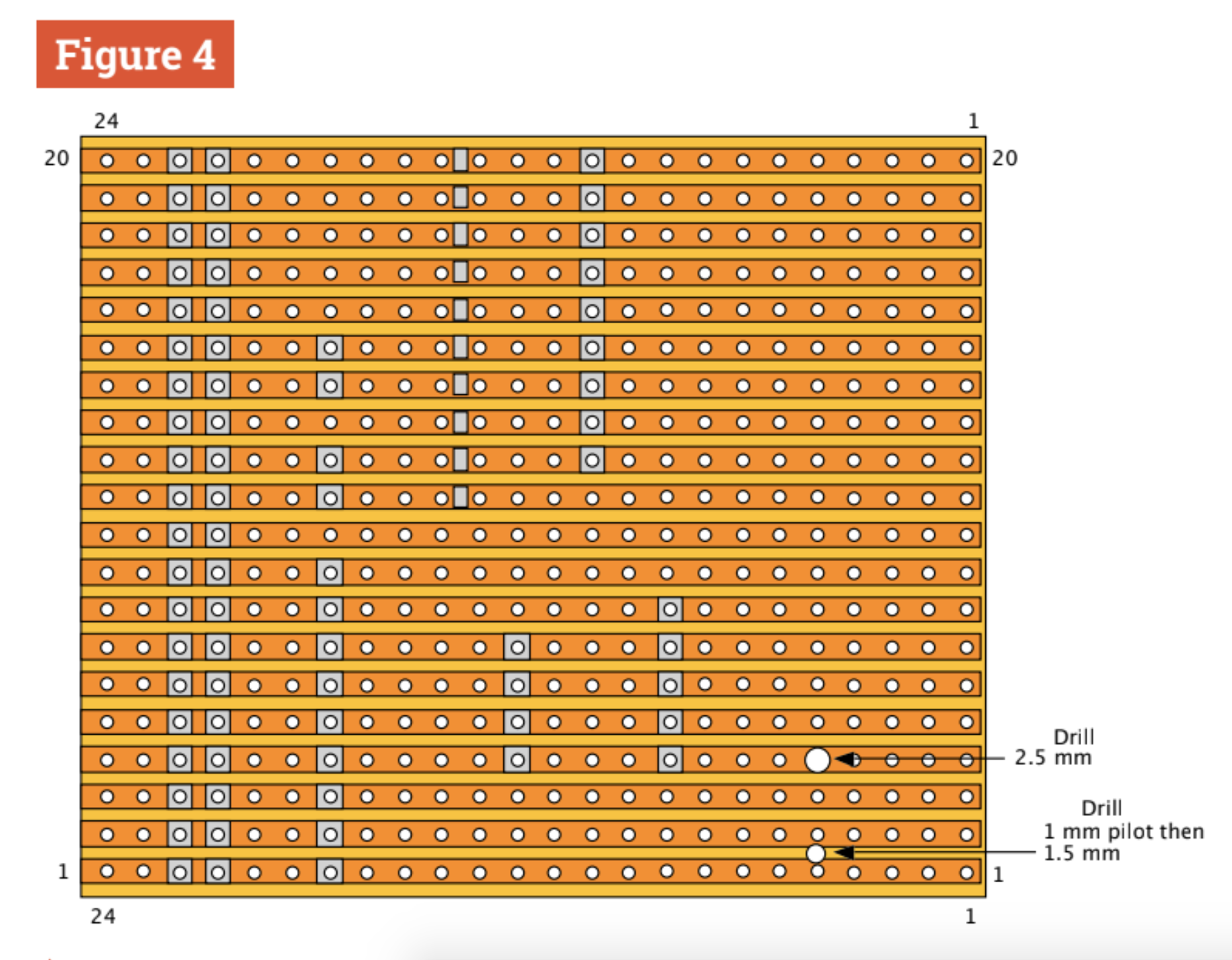
Further construction notes
Note: as always, the physical layout diagram shows where the wires go, not necessarily the route they will take. Here, we don’t want wires crossing the 20-way connector, so the upper four wires use 30AWG Kynar wire to pop under the connector and out through a track hole, without soldering, on the other side. When putting the 20-way IDC pin connector on the ribbon cable, make sure the red end connector wire is connected to the pin next to the downward-pointing triangle on the pin connector. Figure 5 shows a photograph of the control box wiring
Testing the D/A
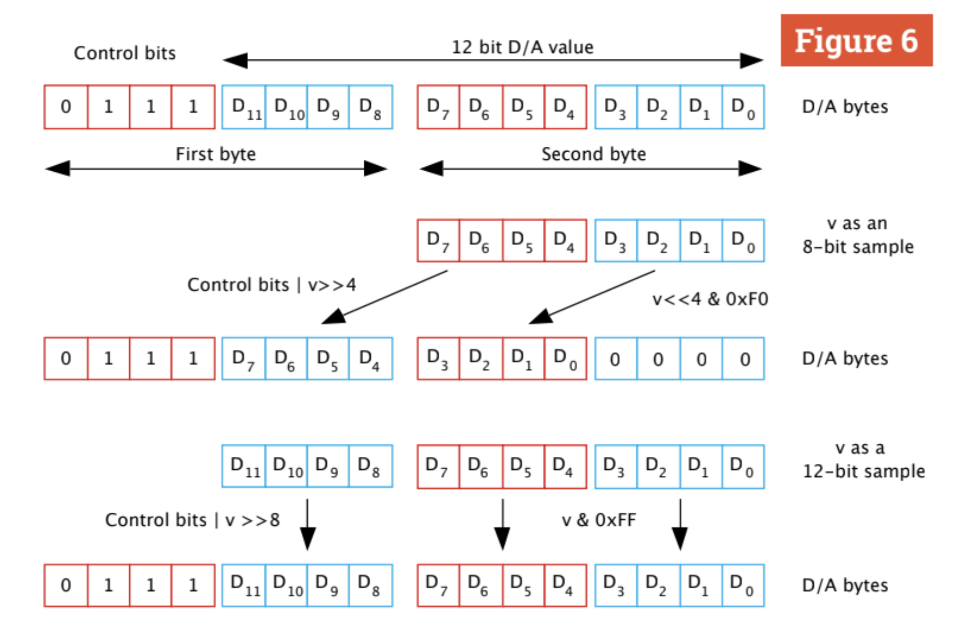
The live_byte_beat.py listing on GitHub is a minimal program for trying out a bytebeat algorithm. It will play until stopped by pressing CTRL+C. The variable v holds the value of the sample, which is then transferred to the D/A over SPI in two bytes. The format of these two bytes is shown in Figure 6, along with how we have to manipulate v to achieve an 8-bit or 12-bit sample output. Note that all algorithms were designed for an 8-bit sample size, and using 12 bits is a free bonus here: it does sound radically different, and not always in a good way.
The main software
The main software for this project is on our GitHub page, and contains 24 Pythonised algorithms. The knobs control the user variables as well as the sample rate and what algorithm to use. You can add extra algorithms, but if you are searching online for them, you will find they are written in C. There are two major differences you need to note when converting from C to Python. The first is the ternary operation which in C is a question mark, and the second is the modulus operator with a percent sign. See the notes that accompany the main code about these.
Why does this work?
There are a few reasons why you would not expect this to work on a Raspberry Pi in Python. The most obvious being that of the interruptions made by the operating system, regularly interrupting the flow of output samples. Well, it turns out that this is not as bad as you might fear, and the extra ‘noise’ this causes is at a low level and is masked by the glitchy nature of the sound. As Python is an interpreted language, it is just about fast enough to give an adequate sample rate on a Raspberry Pi 4.
Make some noise
You can now explore the wide range of algorithms for generating a Glitch Storm and interact with the sound. On our GitHub page there’s a list of useful links allowing you to explore what others have done so far. For a sneak preview of the bytebeat type of sound, visit magpi.cc/bytebeatdemo; you can even add your own algorithms here. For interaction, however, there’s no substitute for having your own hardware. The best settings are often found by making small adjustments and listening to the long-term effects – some algorithms surprise you about a minute or two into a sequence by changing dramatically.
Get HackSpace magazine issue 34 — out today

HackSpace magazine is out now, available in print from the Raspberry Pi Press online store, your local newsagents, and the Raspberry Pi Store, Cambridge.
You can also download the directly from PDF from the HackSpace magazine website.
Subscribers to HackSpace for 12 months to get a free Adafruit Circuit Playground, or choose from one of our other subscription offers, including this amazing limited-time offer of three issues and a book for only £10!
If you liked this project, it was first featured in The MagPi Magazine. Download the latest issue for free or subscribe here.
The post Rotary encoders: Raise a Glitch Storm | Hackspace 34 appeared first on Raspberry Pi.
Comments
Post a Comment